


E87
21.04.2005
Patent E87 - IP Portfolio A1
Basics of Fail-Safe Brake-by-Wire PPC
Inventors: H. Leiber, Dr. T. Leiber
6 Core Innovations
Patent E87DE
Pressure control using adaptive characteristic mapping, adjustment for environmental factors and degrading (loss of signals)
Patent Status : Expired
Patent E87DE1
Basic ABS with current proportional pressure control
Patent Status: Expired
Patent E87DE4
Regenerative Blending with plunger position control (PPC)
Patent Status : Expired
Patent E87DE5
Automated Emergency Braking (AEB)
Patent Status : Expired
Patent E87DE6 - 1
Pedal Gap Brake System with Piston Pressure Control (PPC)
Patent Status : Expired
Patent E87DE6 - 2
Rack and Pinion Drive with Pistron Pressure (PPC)
Patent Status : Expired
Patent E87DE-SA (DE 102005018649)
Keyword: Pressure Control using adaptive characteristic mapping
Claim Features
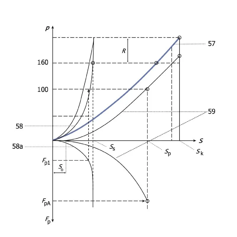
Brake system, comprising an actuating device (30) and a control and regulating device (22),wherein the control and regulating device (22) controls an electromotive drive device (5c, 6, 7, 7a) on the basis of the movement and/or position of the actuating device (30),wherein the electromotive drive device (5c, 6, 7, 7a) displaces a piston (1) of a piston-cylinder system via a non-hydraulic transmission device, so that a pressure is established in the working chamber (4', 4a', 4b') of the cylinder, wherein the working chamber (4', 4a', 4b') is connected to a wheel brake (15, 17) via a pressure line (13),the actuating device (30) displacing the piston (1) in the event of failure of the electric motor drive device (5c, 6, 7, 7a),characterized in thatthe pressure control takes place using a characteristic map,wherein the control and regulating device (22) determines the piston position by means of at least a first sensor and the current by means of a second sensorand adjusts the position of the piston (1) using the characteristic map, the characteristic map being adapted during operation.
Abstract:
The brake system uses an electromotive piston adjustment via a mechanical transmission, whereby the pressure control is adaptive using a characteristic map adapted during operation, which represents the dependence of the brake pressure on the pedal position and is based on sensor values for piston position and motor current.
Technical Relevance:
Both the adjustable pedal characteristics (sport, normal, comfort) of the electro-hydraulic brake booster and environmental influences (air bubbles in the brake fluid, changes in the wheel brake such as slanted wear of the brake pads, friction coefficient fluctuations, knockback, fading, as well as variations in transmission efficiency) require an adaptation of the map. Typically, the characteristic map consists of several parameters (pressure-volume characteristic of the wheel brake, motor torque = f(current), variable transmission efficiency and vehicle deceleration = f(brake pressure)
The adaptation is also relevant if the ESP unit has failed/been deactivated, where the brake booster function remains fully functional. The pedal characteristics change in this case, as the brake force boost is based solely on current consumption and piston travel in the absence of the ESP pressure sensor.
Patent E87DE-TA1 (DE 102005063659)
Keyword: Basic ABS with current proportional pressure control
Claim Features
final legal validity confirmed by 2nd instance BGH
Brake system, comprising an actuating device (30), namely a brake pedal, a pedal travel sensor (38) for detecting a pedal travel of the brake pedal and a control and regulating device (22), wherein the control and regulating device (22) controls a drive device (5c, 6, 7, 7a) with an electric motor (8), taking into account the detected pedal travel,wherein the electric motor drive device is a brushless motor which is controlled by output stages (21) via three lines from a microcontroller (22),wherein the drive device (5c, 6, 7, 7a) displaces a piston (1, 1a) of a piston-cylinder system via a non-hydraulic transmission device, so that a pressure is established in the working chamber (4', 4a', 4b') of the cylinder,wherein the working chamber (4', 4a', 4b') is connected to a wheel brake via a pressure line (13),wherein in the event of failure of the drive device (5c, 6, 7, 7a), the actuating device adjusts the piston (1),characterized bya current sensor (23) for measuring a current of the electric motor,wherein the control and regulating device (22) is designed to carry out a pressure control proportional to the current in accordance with an amplifier characteristic curve,wherein, using the current sensor (23), a position of the piston is approached which corresponds to a specific pressure,wherein the piston-cylinder system is designed to generate a brake pressure build-up and brake pressure reduction for the realization of an ABS control.
Abstract:
The invention is an F-BbW brake system with an actuating device (brake pedal), a pedal travel sensor for detecting the pedal travel, a control and regulating device and a brushless electric motor which, together with a piston-cylinder system and a current sensor, control the brake pressure in proportion to the pedal travel detection and enable ABS control, whereby manual actuation of the piston is possible in the event of failure of the drive device
Technical Relevance
The invention is of high technical relevance for modern brake-by-wire (BbW) systems, as it also represents an early model of a purely electro-hydraulic braking system. It integrates key components such as brushless electric motors, current sensors and an ABS function in the form of an automated cadence braking using motor current as a control parameter. It thus lays the foundation for a safety-critical functionality, especially for vehicles with highly automated driving in accordance with SAE level 3 (source). In addition to the automated cadence braking, the system has an additional fallback level: manual actuation via a conventional brake pedal.
Patent E87DE-TA4 (DE102005063691)
Keyword: Regenerative blending with precise and dynamic Plunger Position Control (PPC)
Claim Features
Method for controlling a brake system with an electromotive drive device (5c, 6, 7, 7a),wherein the electromotive drive device (5c, 6, 7, 7a) displaces a piston (1) of a piston-cylinder system via a non-hydraulic transmission device so that a pressure is established in a working chamber (4', 4a', 4b') of the cylinder,whereby a variable pedal characteristic is adjusted using a sensor system and a displacement simulator,whereby an assignment of the pressure to a pedal force is freely variableand in the case of recuperative braking by means of a generator, taking into account a correction value so that the braking effect of the generator is taken into account,wherein the drive device of the brake system is a brushless electric motor in which three strings are controlled by means of a microcontroller, taking into account a position determination of the piston and a current measurement.
Abstract:
Electro-hydraulic braking system with brushless motor, current and position control of the electric motor for precise pressure control in regenerative braking mode. A correction value is taken into account, which compensates for the regenerative braking torque of the vehicle drive motor in the recuperation management of the braking system.
Technical Relevance:
The technical relevance of this patent lies in the precise pressure control of a regenerative braking system, which enables finely tuned blending between the electromotive recuperation of the vehicle drive motor and the hydraulic braking force.
The system increases the energy efficiency of the vehicle's drive system by recovering kinetic energy during braking, while ensuring a consistent pedal feel during blending. This is achieved by dynamically adjusting the hydraulic brake pressure and so that the actuation force perceived by the driver remains proportional to the actual vehicle deceleration - even during recuperation. This is also known as pedal force blending.
Precise pressure control is particularly important in conjunction with an electro-hydraulic follow-up brake booster with pedal travel simulator, which displays the brake pressure as a function of the pedal travel. In this configuration, any change in hydraulic pressure has a direct effect on the pedal feel perceived by the driver. Therefore, a pressure reduction in the context of recuperative braking must be converted into a proportional adjustment of the amplification power of the brake booster.
Patent E87DE-TA5 (DE 102005063697)
Keyword: Automated Emergency Braking (AEB)
Claim Features
Brake system, comprising an actuating device (33), namely a brake pedal (30), and a control and regulating device (22),wherein the control and regulating device (22) controls an electromotive drive device (7a, 6, 5c) on the basis of the movement and/or position of the actuating device (33),wherein the drive device (7a, 6, 5c) displaces a piston of a piston-cylinder system via a non-hydraulic transmission device,so that a pressure is established in a working chamber (4a') of a cylinder of the piston-cylinder system,wherein the working chamber is connected via several pressure lines (13, 13a) to two or four wheel brakes (15, 17) with wheel brake valves (14, 15),wherein a sensor system and a travel simulator (38) are provided in order to adjust a variable pedal characteristic,wherein the drive device (7a, 6, 5c) is a brushless electric motor which is controlled via three lines by means of a microcontroller (22),wherein, at least in brake-by-wire operation, a pressure increase is freely variable independently of pedal actuation,wherein, at least at the start of braking, a rapid increase in pressure is implemented by fully or partially energizing the drive device (7a, 6, 5c) in order to shorten the braking distance when at least one of the wheel brake valves (14, 15) is fully opened,wherein the brake system is designed to determine a position of the piston for setting a predetermined pressure and then to approach this position.
Abstract:
The invention describes an electrohydraulic fail-safe brake-by-wire (F-BbW) braking system which, by means of a highly dynamic electromotive drive and precise position control of the piston, enables an extremely fast pressure build-up in order to shorten the braking distance.
Technical Relevance
The technical relevance of this patent lies in the ability to realize an extremely fast brake pressure build-up through precise piston position control - and thus automatically initiate very fast braking without driver intervention, which is of central importance for Automatic Emergency Braking (AEB).
This innovation is of central importance in terms of safety, as it enables an immediate reaction to recognized dangerous situations - without the delay caused by human actuation time. While conventional braking systems rely on the driver depressing the brake pedal, this system allows immediate braking intervention following a sensor-based hazard analysis in real time by the AEB.
The braking torque is built up much more dynamically than with conventional braking systems. A brushless electric motor with microcontroller control and field-oriented space vector control (including magnetic flux weakening) controls the piston with high precision. This allows the brake pressure to be built up within a very short time: The patent specifies 50 milliseconds for brake pressure build-up up to 100 bar (TTL) when using two EC motors; 130 milliseconds were achieved in the technical implementation of the IBS Premium prototype with just one EC motor. Today, a pressure build-up time of 150 ms up to 100 bar is standard for modern 1-box EHB braking systems
The combination of automated brake pressure generation and extremely fast pressure build-up defines a new safety standard - comparable to the introduction of ABS and ESP. It forms the basis for today's widespread use of electrohydraulic braking systems with brushless motors in almost all modern vehicles.
In addition, this technology shifts the safety-relevant assessment standard from the classic braking distance to the more comprehensive stopping distance - i.e. the time from when danger is detected until the vehicle comes to a complete stop. This is precisely where the automatic emergency braking function (AEB), which emerged from this innovation, comes into play and is now part of the series standard regardless of the drive concept - whether electric or combustion engine. Further reading: J. Weisse, "Gibt es Verbesserungspotezial für den Bremsassistenten?", XXIII. Internationales µ-Symposium, Oct. 2003, VDI-Fortschrittsberichte, Reihe 12, Nr. 556; and M. Fach, J. Breuer, F. Baumann, M. Nuessle, T. Unselt, "Objektive Bewertungsverfahren für radbremsenbasierte Systeme der Aktiven Sicherheit, XXV. International µ-Symposium, June 2005, VDI-Fortschrittsberichte, Reihe 12, Nr. 597.
Patent E87DE-TA6 (DE 102005063699)
CLAIM 1
Keyword: Pedal Gap Brake System - pressure control with piston position using characteristics mapping
Claim Features
Brake system, comprising an actuating device (30), namely a brake pedal, and a control and regulating device,wherein the control and regulating device controls an electromotive drive device (5c, 6, 7, 7a) on the basis of the movement and/or position of the actuating device (30),wherein the drive device (5c, 6, 7, 7a) of the brake system comprises a brushless electric motor which is controlled via three lines by means of a microcontroller,wherein the drive device (5c, 6, 7, 7a) displaces a piston (1, 1a) of a piston-cylinder system via a non-hydraulic transmission device so that a pressure is established in a working chamber (4', 4a', 4b') of the cylinder,wherein the working chamber (4', 4a', 4b') is connected to wheel brakes via a pressure line (13) or several pressure lines,wherein the actuating device is arranged at a distance from the piston or a spindle;wherein if the drive device (5c, 6, 7, 7a) fails after overcoming an idle travel (SO), the actuating device adjusts the piston (1) or the drive device (5c, 6, 7, 7a),wherein the control and regulating device moves the piston (1) during operation on the basis of a characteristic map into a position which corresponds to a specific pressure according to the characteristic map.
Abstract:
The invention protects a fail-safe brake-by-wire brake system (F-BbW), in which a brushless electric motor controlled by the pedal travel actuates a hydraulic piston via a purely mechanical gearbox in a precise position according to the characteristic map, i.e. piston travel depending on the pedal travel, in order to build up brake pressure, whereby the pedal actuates the piston directly after a defined idle travel in the event of motor failure.
Technical Relevance:
The technical relevance of this innovation lies in the design of a fail-safe brake-by-wire system that enables precise piston positioning using a brushless electric motor and a mechanical gearbox.
This allows the brake pressure to be built up extremely quickly via position-based control of the piston. The defined decoupling between the brake pedal and booster unit via a constructive free travel plays a central role here. This design allows independent measurement of pedal travel and piston travel and makes it possible to move the piston backwards and forwards even at high dynamics without any repercussions on the brake pedal. This reliably prevents unwanted pedal jolts - especially during rapid backward movements.
In addition, the pressure is controlled via motor current and position without a pressure sensor. This basic principle was first introduced to the market in 2013 and has been retained in the 2nd generation.
Patent E87DE-TA6 (DE102005063699)
CLAIM 2
Keyword: Rack and Pinion Drive - pressure control with piston position using characteristics mapping
Claim Features
Brake system, comprising an actuating device (30), namely a brake pedal, and a control and regulating device,wherein the control and regulating device controls an electromotive drive device (5c, 6, 7, 7a) on the basis of the movement and/or position of the actuating device (30),wherein the drive device (5c, 6, 7, 7a) of the brake system comprises a brushless electric motor which is controlled via three lines by means of a microcontroller,wherein the drive device (5c, 6, 7, 7a) displaces a piston (1, 1a) of a piston-cylinder system via a non-hydraulic transmission device, so that a pressure is established in a working chamber (4', 4a', 4b') of the cylinder, wherein the working chamber (4', 4a', 4b') is connected to wheel brakes via a pressure line (13) or several pressure lines,wherein, in the event of failure of the drive device (5c, 6, 7, 7a), the actuating device moves the piston (1) or the drive device (5c, 6, 7, 7a);wherein a rack (5a) is arranged parallel to the piston (1) to drive the piston (1) by means of the drive device (5c, 6, 7, 7a)wherein the control and regulating device moves the piston (1) during operation on the basis of a characteristic map into a position which corresponds to a specific pressure in accordance with the characteristic map
Abstract:
The invention protects a fail-safe brake-by-wire braking system (F-BbW), in which a brushless electric motor controlled by the pedal travel actuates a hydraulic piston via a purely mechanical gearbox in a positionally accurate manner according to the characteristic map, i.e. piston travel as a function of the pedal travel, in order to build up braking pressure, the pedal actuating the piston directly after a defined idle travel in the event of motor failure.
Technical Relevance:
The technical relevance of this innovation lies in a fail-safe brake-by-wire system that combines a brushless electric motor with a cost-effective rack-and-pinion gearbox arranged parallel to the piston, thus enabling an offset arrangement of the booster motor to the piston. This allows the system to be modular and short. In addition, the pressure is controlled via motor current and position without a pressure sensor. This basic theory was introduced to the market in the first-generation electro-hydraulic brake booster.