


E87
21.4.2005
Patent E87 - IP Portfolio A2
Basics of a Fail-Safe Brake by-Wire-System
Inventors: H. Leiber, Dr. Thomas Leiber
5 Core Innovations
Patent E87DE-SA
Pressure control using adaptive characteristic mapping, adjustment for environmental factors and degrading (loss of signals)
Patent Status : Expired
Patent E87DE4
Regenerative blending with Piston Pressure Control (PPC)
Patent Status : Expired
Patent E87DE5
Automated Emergency Braking (AEB)
Patent Status : Expired
Patent E87EP/E87US - 1
Target-Pressure Hold Logic
Patent Status : Expired
Patent E87EP/E87US - 2
PressureMap Plunger - Target Pressure Control via Mapping of Piston Position to Current or Pressure
Patent Status : Expired
Patent Patent E87DE-SA (DE 102005018649)
Keywords: Pressure Control Using Adaptive Characteristic Mapping
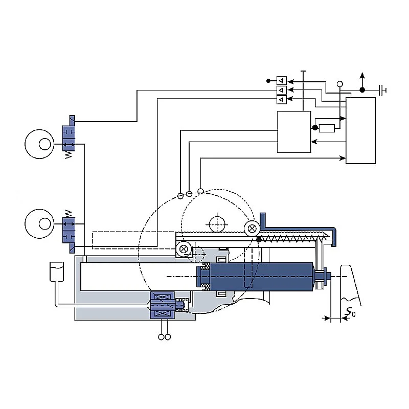
Brake system, comprising an actuating device (30) and a control and regulating device (22),wherein the control and regulating device (22) controls an electromotive drive device (5c, 6, 7, 7a) on the basis of the movement and/or position of the actuating device (30),wherein the electromotive drive device (5c, 6, 7, 7a) displaces a piston (1) of a piston-cylinder system via a non-hydraulic transmission device, so that a pressure is established in the working chamber (4', 4a', 4b') of the cylinder, wherein the working chamber (4', 4a', 4b') is connected to a wheel brake (15, 17) via a pressure line (13),the actuating device (30) displacing the piston (1) in the event of failure of the electric motor drive device (5c, 6, 7, 7a), characterized inin that the pressure control takes place using a characteristic map,wherein the control and regulating device (22) determines the piston position by means of at least a first sensor and the current by means of a second sensorand adjusts the position of the piston (1) using the characteristic map, the characteristic map being adapted during operation.
Claim Features
Abstract:
The brake system uses an electromotive piston adjustment via a mechanical transmission, whereby the pressure control is adaptive using a characteristic map that is adapted during operation and is based on sensor values for piston position and motor current.
Technical Relevance:
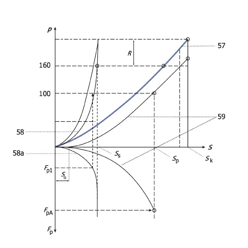
Both the adjustable pedal characteristics (sport, normal, comfort) of the electric brake booster and environmental influences (air bubbles, slanted wear, friction coefficient fluctuations, knockback, fading, variation in transmission efficiency) require an adaptation of the characteristic map, which defines the brake pressure as a function of the pedal travel. Typically, the map consists of several parameters (pressure-volume characteristic of the wheel brake, motor torque = f(current), variable transmission efficiency and vehicle deceleration = f(brake pressure))
The adaptation is also relevant if the ESP unit has failed/been deactivated, where the brake booster function remains fully functional. The pedal characteristics change in this case, as the brake force boost is based solely on the motor current consumption and piston travel in the absence of the ESP pressure sensor.
Patent E87DE-TA4 (DE 102006063691)
CLAIM 1
Keywords: Regenerative blending with precise and dynamic Piston Pressure Control (PPC)
Method for controlling a brake system with an electromotive drive device (5c, 6, 7, 7a),wherein the electromotive drive device (5c, 6, 7, 7a) displaces a piston (1) of a piston-cylinder system via a non-hydraulic transmission device so that a pressure is established in a working chamber (4', 4a', 4b') of the cylinder,whereby a variable pedal characteristic is adjusted using a sensor system and a displacement simulator,whereby an assignment of the pressure to a pedal force is freely variableand, in the case of recuperative braking by means of a generator, taking into account a correction value so that the braking effect of the generator is taken into account,wherein the drive device of the brake system is a brushless electric motor in which three strings are controlled by means of a microcontroller, taking into account a position determination of the piston and a current measurement.
Claim Features
Abstract:
Electro-hydraulic fail-safe brake-by-wire (F-BbW) brake system with brushless motor, current and position control for precise pressure control in regenerative braking mode. This takes into account a correction value that compensates for the regenerative braking torque in the recuperation management of the braking system.
Technical Relevance:
The technical relevance of this patent lies in the precise pressure control of a regenerative braking system, which enables finely tuned blending between the electric motor recuperation and the hydraulic braking force.
The system increases energy efficiency by recovering kinetic energy during braking, up to a high regenerative vehicle deceleration, while providing a consistent pedal feel. This is achieved by dynamically adjusting the hydraulic brake pressure so that the actuation force perceived by the driver remains proportional to the actual vehicle deceleration, even during changes in the regenerative braking effect of recuperation.
Precise pressure control is particularly important in conjunction with an electro-hydraulic brake booster with pedal travel simulator. In this configuration, any change in hydraulic pressure has a direct effect on the pedal feel perceived by the driver. Therefore, a pressure reduction in the context of recuperative braking must be converted into a proportional adjustment of the amplification power of the brake booster. This requires extremely precise modeling of the hydraulic system and its physical interactions. For readers interested in more detail, we recommend taking a look at patent EP2536605, which clearly describes the physical principles and control relationships of the electrohydraulic regenerative brake booster.
Patent E87DE-TA5 (DE 102005063697)
Keywords: Automated Emergency Braking (AEB)
Brake system, comprising an actuating device (33), namely a brake pedal (30), and a control and regulating device (22),wherein the control and regulating device (22) controls an electromotive drive device (7a, 6, 5c) on the basis of the movement and/or position of the actuating device (33),wherein the drive device (7a, 6, 5c) displaces a piston of a piston-cylinder system via a non-hydraulic transmission device,so that a pressure is established in a working chamber (4a') of a cylinder of the piston-cylinder system,wherein the working chamber is connected via several pressure lines (13, 13a) to two or four wheel brakes (15, 17) with wheel brake valves (14, 15),wherein a sensor system and a travel simulator (38) are provided in order to adjust a variable pedal characteristic,wherein the drive device (7a, 6, 5c) is a brushless electric motor which is controlled via three lines by means of a microcontroller (22),wherein, at least in brake-by-wire operation, a pressure increase is freely variable independently of pedal actuation,wherein, at least at the start of braking, a rapid increase in pressure is implemented by fully or partially energizing the drive device (7a, 6, 5c) in order to shorten the braking distance when at least one of the wheel brake valves (14, 15) is fully opened,wherein the brake system is designed to determine a position of the piston for setting a predetermined pressure and then to approach this position.
Claim Features
Abstract:
The invention describes an electro-hydraulic fail-safe brake-by-wire (F-BbW) braking system which, by means of a highly dynamic electromotive drive and precise position control of the piston, enables extremely rapid pressure build-up in order to shorten the braking distance.
Technical relevance:
The technical relevance of this patent lies in the ability to realize an extremely fast brake pressure build-up through precise piston position control - and thus automatically initiate very fast braking without driver intervention, which is of central importance for Automatic Emergency Braking (AEB).
This innovation is of central importance in terms of safety, as it enables an immediate reaction to recognized dangerous situations - without the delay caused by human actuation time. While conventional braking systems rely on the driver pressing the brake pedal, this system allows immediate braking intervention after a sensor-based hazard analysis in real time by the AEB.
The braking torque is built up much more dynamically than with conventional vacuum brake boosters. A brushless electric motor with microcontroller control and field-oriented space vector control (including magnetic flux weakening) controls the piston with high precision and maximum motor speed. This allows the brake pressure to be built up within a very short time: The patent specifies 50 milliseconds for brake pressure build-up up to 100 bar (TTL) when using two EC motors; 130 milliseconds were achieved in the technical implementation of the IBS Premium prototype with just one EC motor. Today, a pressure build-up time of 150 ms up to 100 bar is standard for modern 1-box EMS braking systems
The combination of automated brake pressure generation and extremely fast pressure build-up defines a new safety standard - comparable to the introduction of ABS and ESP. It forms the basis for today's widespread use of electrohydraulic braking systems with brushless motors in almost all modern vehicles.
In addition, this technology shifts the safety-relevant assessment standard from the classic braking distance to the more comprehensive stopping distance - i.e. the time from when danger is detected until the vehicle comes to a complete stop. This is precisely where the automatic emergency braking function (AEB), which emerged from this innovation, comes into play and is now standard, regardless of the drive concept - whether electric or combustion engine. Further reading: J. Weisse, "Gibt es Verbesserungspotezial für den Bremsassistenten?", XXIII. Internationales µ-Symposium, Oct. 2003, VDI-Fortschrittsberichte, Reihe 12, Nr. 556; and M. Fach, J. Breuer, F. Baumann, M. Nuessle, T. Unselt, "Objektive Bewertungsverfahren für radbremsenbasierte Systeme der Aktiven Sicherheit, XXV. International µ-Symposium, June 2005, VDI-Fortschrittsberichte, Reihe 12, Nr. 597.
Patent E87EP (EP1907253)
CLAIM 1
Keywords: MUX ABS with Target-Pressure Hold Logic
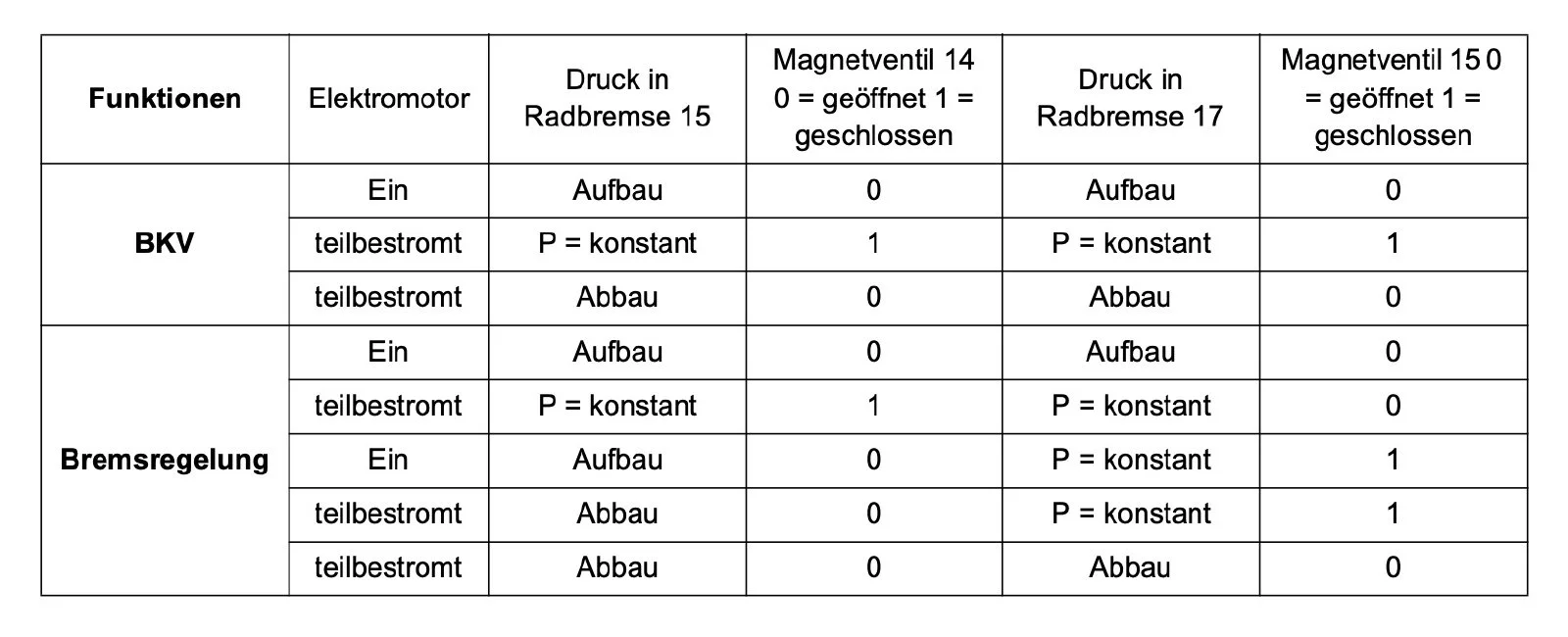
Brake system, having an actuating device (30), in particular a brake pedal, and a control and regulating device,wherein the control and regulating device controls an electromotive drive device (5c, 6, 7, 7a) on the basis of the movement and/or position of the actuating device (30),wherein the drive device (5c, 6, 7, 7a) displaces a piston (1, 1a) of a piston-cylinder system via a non-hydraulic transmission device firmly coupled to the piston (1, 1a),so that a pressure is established in the working chamber (4', 4a', 4b') of the cylinder, the working chamber (4', 4a', 4b') being connected to a wheel brake via a pressure line (13),wherein a valve (14, 16) controlled by the control and regulating device (22) is arranged in the pressure line (13) to each wheel brake (15, 17), and if the drive device (5c, 6, 7, 7a) fails, the actuating device (30) adjusts the piston (1) or the drive device (5c, 6, 7, 7a),wherein the electromotive drive device displaces the piston (1) via a rotor (66) and a spindle drive acting as a reduction gear, and that the piston (1) generates the required pressure change for the brake force boosting (BKV) and the anti-lock braking system (ABS),wherein the valve (14, 16) closes after reaching the required brake pressure in the brake cylinder (15, 17) and is also open in ABS operation both for setting a new lower and a new higher brake pressure.
Claim Features
Abstract:
The invention relates to a brake system with an electromotor-actuated piston of a piston-cylinder system, in which a non-hydraulic transmission moves the piston to generate pressure for brake force boosting and ABS function, whereby each brake pressure is dynamically set by opening the respective valve via wheel-selective valves controlled by a control and regulating device and is kept constant by closing after reaching the target value, thus enabling sequential ABS pressure control in multiplex operation - with guaranteed immediate emergency actuation in the event of a fault.
Technical relevance of the MUX control strategy:
The above-mentioned patents formed the basis for the development of a new type of ABS prototype with pressure control in the closed brake circuit using so-called hydraulic multiplex operation. This process enabled impressively short braking distances on roads with low coefficients of friction - especially on ice and snow, and on µ-split roads.
However, multiplex control reached its limits at higher coefficients of friction, for example on asphalt: In addition to physical challenges caused by the larger pressure jumps and time delays of hydraulic multiplexing, NVH problems (noise and vibrations) also arose, particularly when pressure was reduced simultaneously in several wheel brakes with different pressure levels. This resulted in equalizing flows between the wheel brake cylinders within the closed system, which had a negative control and acoustic impact and impaired ride comfort.
Another obstacle to the series launch was the increased dynamic requirement for the electric motor, which was necessary in multiplex operation in order to reliably implement rapid pressure changes. These requirements could not be met by the electric motors available on the market at the time of early development. A new type of motor was therefore required - in particular a DAG motor - which was initially not in the portfolio of common motor manufacturers. The associated investments in development and industrialization increased the system costs and slowed down economic implementation. However, a separate study by BMW AG showed that the unit costs of the DAG motor in series production were competitive and not disadvantageous compared to conventional solutions.
Despite the lack of market penetration, the concept of the closed brake circuit - especially for 2-channel pressure actuators for a vehicle axle - continues to have a high technological relevance. Thanks to the model-based clarity and physical predictability of such systems, new potential for automation and control quality is opening up, especially in conjunction with artificial intelligence and model-predictive control algorithms.
Patent E87EP (EP1907253)
CLAIM 2
Keywords: Target Pressure Control via Mapping of Piston Position to Current or Pressure
Method using a brake system according to one of the preceding claims,characterized in that a map is applied when the vehicle is put into operation or during operation,in which different motor currents or pressures are assigned to positions of the piston,wherein, during operation, a position of the piston (1) is then approached in accordance with an amplifier characteristic curve, which position corresponds to a specific pressure in accordance with the characteristic map.
Claim Features
Abstract:
The method describes the creation of a characteristic map which assigns piston positions to specific motor currents or pressures, so that during operation the piston position for the desired brake pressure is specifically approached via booster characteristic curve.
Technical Relevance:
This patent describes the principles of current-proportional pressure control on the basis of a characteristic map (calculation of pressure at the piston as a function of the current flow to the motor), but its formulation is limited to claim 1 of the patent (ABS MUX operation). Current-proportional pressure control was therefore pursued further in a divisional application (E87DE1, DE 102005063659) and is now a core component of brake booster control in electric brake boosters.